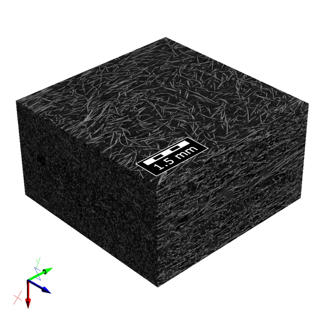
Analysis of a Long Fiber Reinforced Thermoplastic

Import of a µCT scan, identification of single fibers, pore analysis and prediction of stiffness

Fiber-reinforced composites play an increasingly important role in lightweight applications. Among these composites, short and long fiber-reinforced thermoplastics are highly popular as they combine comparably low material cost, efficient production processes, e.g. injection molding, and good mechanical properties, especially if long fibers are used.

These materials present a complex microstructure with two material phases (fibers and polymer) and usually, an unwanted third phase (pores). Additionally, the manufacturing process itself influences the microstructure e. g. by changing the fiber orientation or the fiber length. In injection molding, the filling of the mold leads to a characteristic layer structure, which in the simplest case, consist of two outer regions and a core. In the outer regions, high shear velocities lead to an alignment along the flow direction. The slower, laminar flow in the core region causes a transverse to random orientation of the fibers. This effect produces complex fiber orientations in the composite. Using µCT-scans , the fibers and pores in the resulting microstructure can be analyzed thoroughly to better understand the microstructure of injection molded materials.


In this study, a µCT-scan of a glass fiber reinforced polypropylene made by the Leibniz-Institut für Verbundwerkstoffe GmbH (IVW) was analyzed. It has a fiber volume content of 13%, a tensile modulus of 6 GPa, and an elongation at break of 2.5% [1]. The specimen was an injection molded type 1A shouldered test bar and mechanical testing was performed according to DIN EN ISO 527-1 to -5 [1].

  • Import and segmentation of the µCT scan
  • Identification of single fibers by FiberFind-AI
  • Identification of the pores using PoroDict
  • Analysis of mechanical properties with ElastoDict

You can also easily apply these steps to your material in GeoDict.


The following GeoDict modules were used

Authors and application specialists

Dr.-Ing. Martina Hümbert

Senior Business Manager
for Digital Materials R&D

Andreas Grießer, M.Sc.

Senior Business Manager
for Image Processing and Image Analysis

Dr.-Ing. Oliver Rimmel

Business Manager
for Digital Materials R&D

Book appointment online

Import and segmentation of the µCT scan

Approach

In a first step, the gray-value images of the scan were imported in GeoDict for segmentation. A non-local means filter was applied (patch radius: 1, search radius: 3, filter strength: 0.2) to improve the image quality. The segmentation led to a fiber volume content of 13.2% and a significant number of pores, namely 1.3%. The resulting model has a size of 1500x1500x800 voxels.


The following GeoDict modules were used

Identification of the individual fibers

Approach

The fibers in the segmented scan were identified using a self-trained neural network. For technical details see [2]. The fiber analysis delivers -among others- fiber diameter and fiber orientation. The fiber orientation was also analyzed through the thickness of the scan. This showed the typical three-layer structure of injection molded materials, as shown in Figure 2. All fibers with an angle to the x-direction larger than 25° were labeled in red color.


The following GeoDict modules were used

Analysis of the pores

Approach

The pores were identified using a watershed-based algorithm. Their shape, diameter, and location was analyzed. The voids are mainly located in the inner region in which the fibers are not aligned to the flow direction and have a mean diameter (diameter of volume-equivalent sphere) of 237.367 µm with a standard deviation of 97.4617 µm.


The following GeoDict modules were used

Prediction of mechanical properties

Approach

The mechanical properties of the scan were analyzed and the result was compared with the tensile tests performed at IVW. For this purpose, we used the finite-difference-based voxel solver FeelMath developed by Fraunhofer ITWM and integrated in GeoDict. The elastic moduli in the direction of injection were used for comparison. This is also the main fiber direction in the surface layers. The elastic moduli of the materials used for the simulation, the IVW-tested sample and the segmented scan simulated in GeoDict are listed in the table on the right.

In addition, the influence of the pores on the stiffness was analyzed. For this purpose, the pores in the segmented scan were also filled with polypropylene. The modulus of elasticity with pores was 5.80 GPa and the modulus of elasticity without pores was 5.88 GPa. This minimal increase shows that the pores do not have a significant effect on the elastic modulus, although they appear to be quite large. However, they are mainly located in the core layer, where the less aligned fibers do not contribute to the elastic modulus to the same extent as the more straight fibers in the outer layers.


The following GeoDict modules were used

References

[1] H. Andrä, M. Gurka, M. Kabel, S. Nissle, C. Redenbach, K. Schladitz, O. Wirjadi: Geometric and Mechanical Modeling of Fiber-Reinforced Composites. In: D. Bernard, J.-Y. Buffière, T. Pollock, H.F. Poulsen, A. Rollett, M. Uchic (Eds.): Proceedings of the 2nd International Congress on 3D Materials Science (3DMS). Annecy, 29.06.-02.07, pp. 35–40, John Wiley & Sons, 2014.

[2] A. Grießer, R. Westerteiger, M. Azimian, B. Planas, A. Wiegmann: Identification of Fiber Characteristics of a Filter Media based on Artificial Intelligence (AI) with GeoDict. Downloaded from https://doi.org/10.30423/report.m2m-2020-01, 2020.


Acknowledgement

We thank the Leibniz-Institut für Verbundwerkstoffe for providing the µCT scan.