Modeling of fiber media, nonwovens, and fiber-reinforced composites
FiberGeo
FiberGeo generates advanced 3D digital models of materials, called digital twins. These materials include spunbonded fabrics, carded nonwovens, filter media, laminate structures, insulation materials, gas diffusion layers (GDL), and fiber-reinforced composites. The modeling process in FiberGeo begins with the input of a statistical description of the material that includes key parameters such as fiber shape, fiber diameter and length distributions, curvature, and fiber orientation distribution.
In instances where statistical input parameters are unavailable, our innovative FiberFind module is the solution. From 3D scans of actual materials, FiberFind rapidly identifies the necessary parameters, guaranteeing precision and dependability in the modeling process with FiberGeo.
The digital 3D microstructure model, or digital twin, offers an unparalleled level of detail, enabling comprehensive analyses comparable to those obtained from traditional µCT scans. Its analysis capabilities include the computation of pore-size distribution (with the PoroDict module) and the simulation of permeability (with the FlowDict module).
The digital twins generated with GeoDict stand out due to their remarkable versatility. Unlike a single CT-scan, a digital twin based on a statistical model is an extremely effective tool for digital material design. A digital twin enables the exploration of diverse material structures by digitally manipulating the underlying parameters.

3D microstructure of Gas Diffusion Layers (GDL)
- Create GDL with curved or straight fibers
- Add realistic binder distributions
(a) 3D image of a GDL model generated with FiberGeo
(b) 2D image of a GDL model generated with FiberGeo

3D microstructure of composite materials
- Modelling of short and long fiber-reinforced materials
- Modelling of laminates
(a) Digital twin of a short glass-fiber composite
(b) Carbon fiber laminate

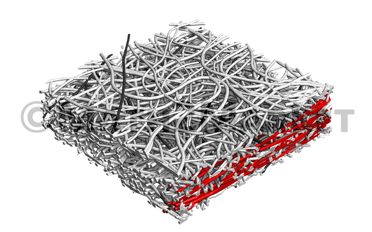
3D microstructures of fibrous filter media
- Modelling of multilayer fibrous filter media
- Modelling of gradients and heterogeneity
- Modelling of complex fiber distributions
(a) Layered fibrous filter material
(b) Fine-layer and support-layer of a face mask

3D microstructure of nonwovens
- Modelling of complex curved fibers
- Modelling of heterogenous fiber distribution
and gradients - Combine fibrous media with grains or woven
materials
(a) Digital twin of a nonwoven material
(b) Compressed rockwool
(c) Dewatering felt
FiberGeo includes multiple options to create and modify fiber media.
Create Fibers places fibers of a specified shape and size distribution into a 3D domain until a given solid volume percentage (or a similar stopping criterion) is reached. The fibers are created with overlap, or optionally, are densely packed without overlap. Multiple fiber shapes and material phases are available. Additionally, fibers can be added to an already existing 3D microstructure model.
The fiber profiles can take various shapes, including circular, elliptical, rectangular, trilobal, or custom-defined with randomly distributed parameters. Fibers may be either solid or hollow and can be modeled as infinitely long or with a random length distribution. Both straight and curved fibers can be simulated, with the option to apply random orientation distributions. Additionally, fiber bundles can be created for more complex modeling.
Pile Fibers allows to pile fibers of a specified shape and size distribution onto a flat surface or into a pre-existing 3D microstructure model. During the piling process, the fibers are arranged in a non-overlapping manner, with each other and with the existing geometry. Additionally, users have the option to specify an isolation distance between the fibers, if required.
The Add Binder feature enables the inclusion of realistic binder distributions into any existing 3D microstructure model. For example, those created using the Create Fibers option. The binder distribution is fully customizable and can be anisotropic, with the option of following a gradient distribution.

FiberGeo
Following Modules are often used in combination with FiberGeo:
| Image Processing and Image Analysis | ImportGeo-Vol | |||||
| Material Analysis | PoroDict + MatDict | FiberFind | ||||
| Modeling & Design | ||||||
| Simulation & Prediction | ConductoDict | DiffuDict | ElastoDict | FlowDict | SatuDict | FilterDict |
| Interfaces | ExportGeo-CAD + MeshGeo |
Suitable modules depend on the concrete application.