Simulating Water Flow for Cylindrical Catalysts
In this section, we show how to simulate water flow through the reactor since we want to investigate the pressure drop of a liquid reactant along the catalysts.
Make sure, that the piled structure is still loaded in memory and displayed in the Visualization area of GeoDict. Otherwise you can load the structure from Results-M2M\Pile-Cylinder_M2M\Structure.gdt.
- In the menu bar, select Predict → FlowDict.
- In the FlowDict section, select Stokes(-Brinkman) from the drop-down menu and click Edit….
- In the Solver Options dialog, set the Result File Name to Stokes-Cylinder.gdr and adjust the fluid under the Constituent Materials tab by clicking on Set all Fluids to….
- In the opening window select Water as new material for the fluids and confirm with OK.
- Go to the Boundary Conditions tab.
- Check that the Z-direction is selected as Computation Direction.
- For the Domain Boundary Conditions in Longitudinal Direction (in flow direction), we check Symmetric (Dirichlet).
- We predefine a Mean Velocity of 0.1 m/s for the fluid, so that the pressure drop will be computed.
- In the Solver tab, choose LIR as the solver. We do not change any of the default settings.
- Click OK to close the solver options window and then Run in the FlowDict section to start the simulation.
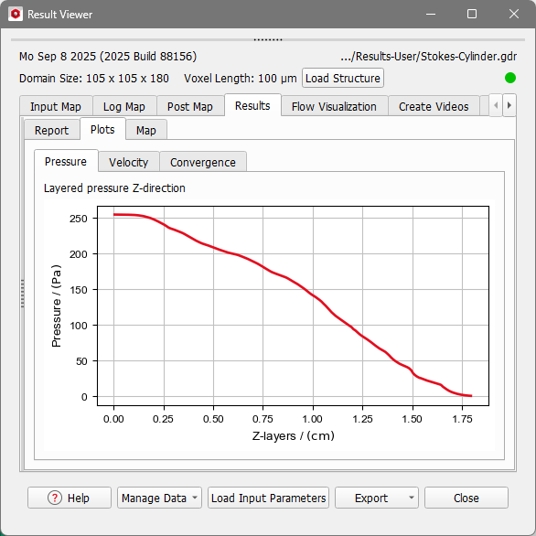
After the simulation is finished, the Result Viewer of the Stokes-Cylinder.gdr result file opens automatically. In the Results → Report subtab, the pressure at the bottom of the reactor (254 Pa) is displayed.
- In the subtab Plots, observe the pressure drop plotted over the layers in Z-direction.
- Go to the Flow Visualization tab and click Load to visualize the volume fields.
- Confirm with OK.