Particles Tab
|
Experimental setup and material parameters: As test dust, we use ISO 12103-1 A3 Medium Test Dust (Arizona Test Dust) which has a specific density of 2650 kg/m³. The bulk density of loose A3 dust is 1.025 kg/m³, which corresponds to a solidity of 38.7 %. During depth filtration phase, 11 % of the filter materials pore volume become filled with dust particles. The fractional filtration efficiencies range from 15.5 % for 1 µm sized particles to 100 % for larger particles (table with measured data is given) The thickness of the filter medium is 180 µm (according to the CAD structure model). |

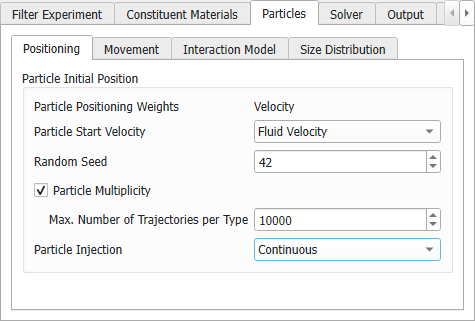
- Under the Particles tab, select the Positioning tab and set the Max. Number of Trajectories per Type to 10000. Additionally, set Particle Injection to Continuous in the drop-down menu.
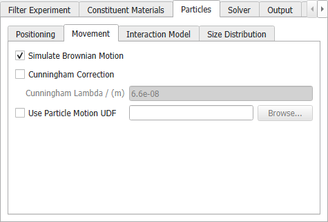
- In the Movement subtab, deselect the Cunningham Correction, as this is only relevant for air filtration.
- Under the Interaction Model subtab, the Pass Through Model defines for each material if particles can pass through the material and if they can be filtered inside of the material.
- In the fluid phases (ID 00, ID 06, ID 07), set the Pass Through Model to All particles pass, because those voxels are open for particle movement.
- The Pass Through Models of the solid materials are automatically set to Impassable. No filtration may happen inside of those voxels.
- In the porous material (ID 05) that describes the filter, the depth filtration properties are described by the Pass Through Model. For simplicity, we assume a Const. efficiency model here, which means that the filtration efficiency will not change over time. For every particle size, the efficiency has to be entered in the Size Distribution table as will be described below.
- In the Max. Particle Packing Density column we have to define for all passable materials how many particles can be deposited inside of a voxel. The volume fraction entered here defines when the voxel is filled, i.e., when no further particles can enter this voxel. When this volume fraction is reached, the voxel turns impassable and further particles will collide at the voxel surface.
- In the fluid phases (ID 00, ID 06, ID 07), set the Max. Particle Packing Density to 0.387, which is the solidity of loose A3 dust. We do not expect dendritic growth of the filter cake in oil filtration, so we make the assumption here that the cake reaches the solidity of the loose dust.
- In the porous material (ID 05), set the Max. Particle Packing Density to 0.11 which means that 11% of the filter volume can be filled with dust particles.
- In the Collision Model column, we have to define what happens when particles collide with an impassable material - either an initially solid material or an initially passable voxel that is maximally filled.
- For the solid materials, we set the the Collision Model to Sieving, meaning that all particles bounce off the surface of the casing. The Restitution parameter describes how much energy is lost in such a collision – this parameter must be set in the Size Distribution table as described later.
- For pore and porous materials, we set the Collision Model to Caught on first touch, meaning that particles will always deposit on a filter cake surface if that filter cake has already reached its maximum possible solidity.
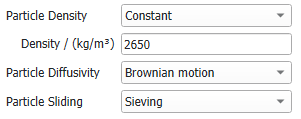
- Finally, adjust the Particle Density to a Constant value of 2650 kg/m³.
- We want to simulate oil filtration using the ISO 12103-1 A3 medium sized test dust. Therefore, go to the Size Distribution subtab of the Particles tab and click Import. By default, the dialog opens in the FilterDict folder of the GeoDict installation folder. Select the ISO-12103-1-A3-Medium.txt test dust distribution file (it is also provided in the Input-Data folder of this tutorial).
- Next, we set all the Restitution values to 0.5 - meaning that particles lose half their initial speed when colliding. For this, enter 0.5 in the first row for all restitution columns, then click the title of the column Restitution (in [0,1]) for Sieving.
A message pops up asking if setting all values in the selected column to the value in the first row. Click Yes to avoid having to type 0.5 in all the rows, since the value is the same for all. Do the same for all other columns of Restitution.
- Next, we define the filtration properties of the filter media (here, material ID 05). Enter 180e-6 m as Media Thickness for Const. efficiency in the first row and click on the column title to set the same value in all rows of the column.
- Open the FractionalFiltrationEfficiencies.xlsx file that you can find in the Input-Data folder of this tutorial. In Excel. mark the filtration efficiencies in the column B, then press Ctrl+C to copy the data. In GeoDict, click into the first row, then press Ctrl+V to insert the data into the column.