Quality Control
Before the gray value image is segmented, a quality control is appropriate.

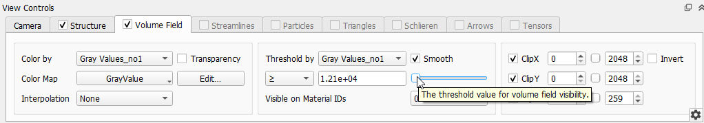
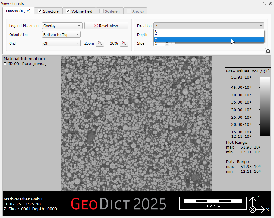
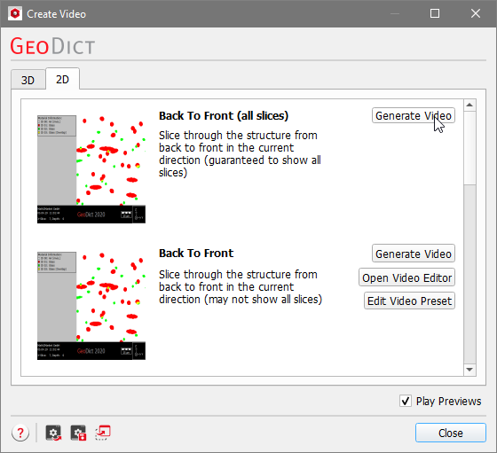
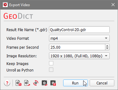
To generate a video slicing through the sample in 2D, switch now to the GeoDict GUI, where the gray value image is visualized as a volume field. Now, the empty domain around the gray value image must be cropped, too. To better visualize this, the gray value is first shown as 3D image and later the visualization is changed to 2D. The view can be changed using the 2D and 3D buttons in the toolbar. If the gray value image is not visible, in the View Controls panel switch to the Volume Field tab and move the threshold slider all the way to the left. Select Model - ProcessGeo from the menu bar. In the ProcessGeo section, on the bottom left, select Crop, Embed & Add Layers from the first pull-down menu and Crop from the second. Click Edit. 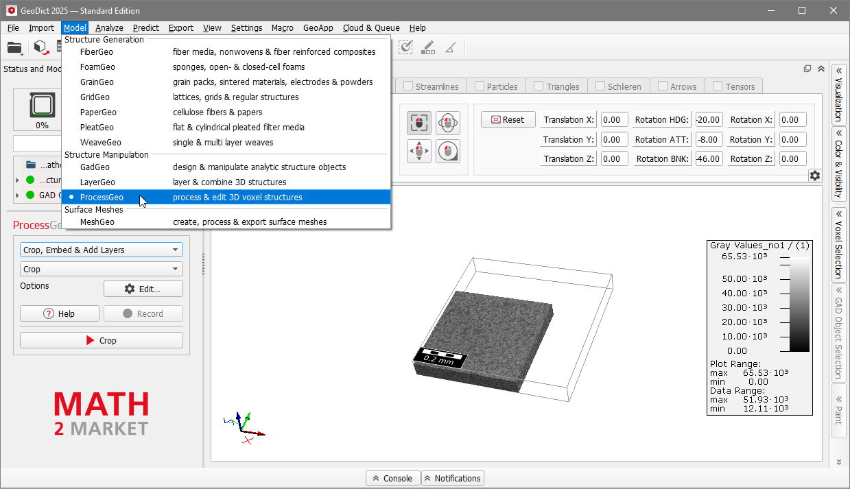
 |
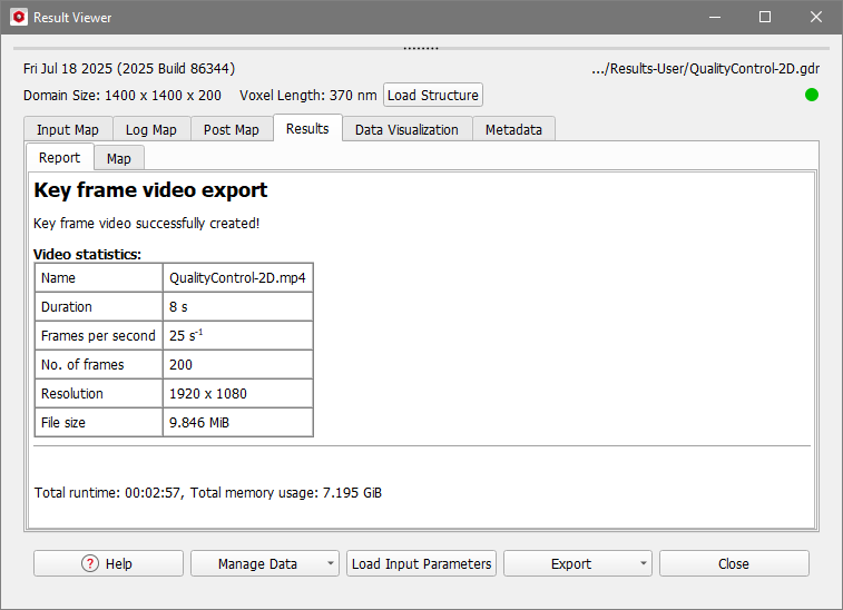
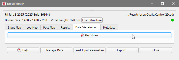
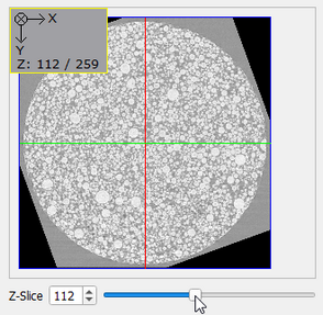
There is no flickering in the image and the slices are aligned well. The resolution of the individual particles is good, but the carbon black and binder phase cannot be differentiated from the active material by gray value. Thus, a neural network is needed to distinguish between the two phases, as described in the second part of this tutorial series. To again visualize the sample in 3D, select View - 3D Rendering from the menu bar or click on the 3D icon as described here. The gray scale image is then displayed in 3D. Use the mouse cursor to turn the structure and watch it from all sides. |
©2026 created by Math2Market GmbH / Imprint / Privacy Policy