Step 2: Define Inlet and Outlet
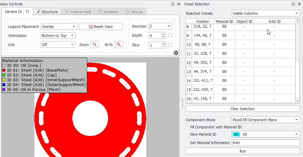
- In this CAD model, the inlets are the outer openings in Z-direction. To define these openings as inlet, switch to the 2D-view by clicking the
 icon. Under the Camera tab of the view controls panel, choose Direction Z as axis and set Slice to 1.
- Click the
 icon in the toolbar to edit voxels. In the opening Voxel Selection dialog shown on the right, choose Flood-Fill Component Plane as Component Mode. Select 06 Oil as New Material ID and write Inlet into the Set Material Information edit box.
- With the Voxel Selection dialog still open, click anywhere inside the inlet planes in the Visualization area of the GeoDict GUI. To select all the 16 inlet planes, hold CTRL + click in each plane. This action marks these voxels in the inlet and now their Position coordinates appear in the Selected Voxels field.
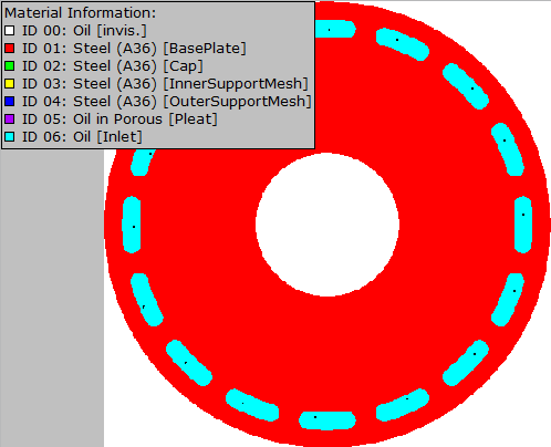
- Then click Run to have the Flood-Fill Component Plane option fill each of the slices with the New Material ID (cyan, ID 06). The inlet openings are now assigned to Material ID 06:
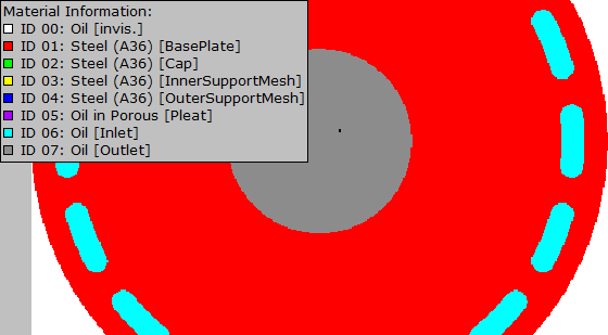
- Now, define the outlet plane following the same steps. To do so, click Clear Selection, and select now a single voxel in the central outlet plane.
The component mode remains as Flood-filled Component Plane. Select 07 Oil as New Material ID and enter Outlet in the Set Material Information edit box.
- Click Run to assign the outlet plane to Material ID 07.