Generation of cylindrical pleated cartridges and digital optimization of filter flow performance
Over the last years, developments in the digital design of new geometries to optimize filtration relevant parameters at the micro-scale have gained significant importance. Also on larger scales, as when simulating flow and filtration on filter elements including housing, the use of Computer-Aided-Design (CAD) is of keen interest.
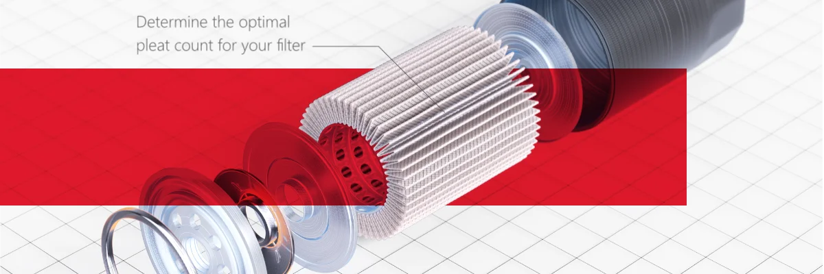
However, performing systematic digital experiments on varying geometrical setups requires the generation of these structures as CAD individually and importing these samples one by one. Here, we present our newest software development within the PleatGeo module, that makes it possible to generate a wide variety of cylindrical pleated structures with changing pleat count and pleat thickness, as well as number of porous layers.
Suitable cylindrical pleated structures are created easily, and the resulting filters can be digitally investigated for their pressure drop and other filtration relevant parameters, by solving the (Navier)-Stokes-Brinkman equation. In this study, we run simulations on a filter structure with different pleat counts and volumetric flow rates. We find find the local minimum of the pressure drop and the ideal configuration between filter area and pleat count. So, the performance of filter prototypes can be tested digitally without relying on expensive producing and testing phases. Only promising prototypes undergo measurements at the testbench. These systematic simulations may be run using cloud applications to increase the productivity. In this way, systematic simulations with varying geometries or flow rates can be run simultaneously.
We proceeded in the following steps:
- Import of the CAD geometry
- Generation of cylindrical pleat structures using PleatGeo
- Simulation of the filter flow performance
What was the result?
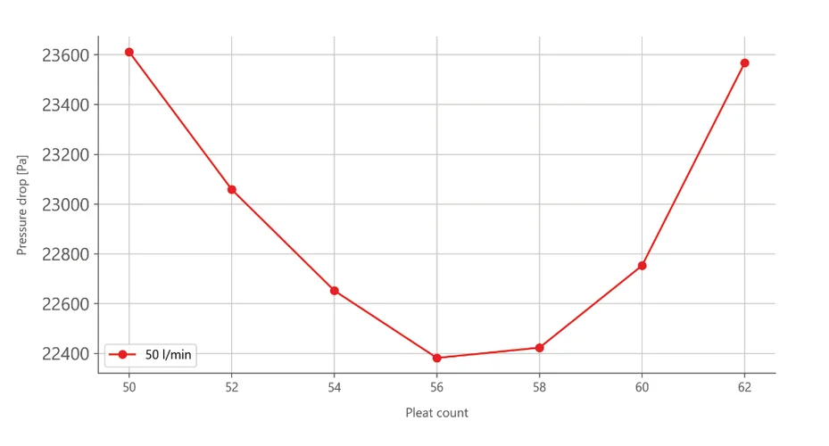
- The results of the parameter study revealed the optimal number of 56 pleats for this filter.
- The simulations in this study were performed on a standard 16-core workstation.
- The simulations required approximately 67 GB of RAM and a simulation time of approximately 1.4 hours each.
What does this mean for our customers?
- Efficiently test the influence of different filter pleat configurations digitally.
- Costly and time-consuming measurements on the test bench could be limited to the promising prototypes.
- Time-to-market performance.
- Ready for deployment in the cloud.
- Perform parametric studies, including changing pleat counts, volumetric flow rates, or different fluid viscosities.
Approach
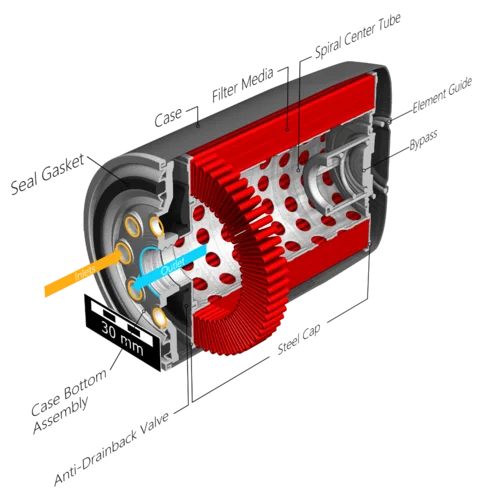
In this application case, a simple oil filter is used for demonstration. The filter structure, as file in .stl format, is imported into the simulation software GeoDict using the ImportGeo-CAD module.
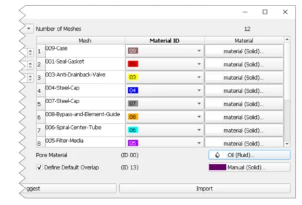
In this process, each material ID of the imported filter geometry is assigned a different color.
In a consecutive step, each material ID can be assigned to different material parameters through the built-in material database. Additionally, the inlets and outlets - here located in Fig. 1 at the Case Bottom Assembly, marked by the orange (Inlet) and blue (Outlet) arrows -, as well as the fluid, need to be specified.
During the import and voxelization step, GeoDict returns feedback regarding the watertightness of the geometry, which is essential for a successful simulation.
If the structure is initially not entirely enclosed, it is possible to seal the geometry with built-in functions of GeoDict, which saves time, instead of fixing the initial input data separately.
For further simulations or parametric studies, the filter structure geometry can be saved to a file, to avoid having to reimport the .stl file for each additional simulation.
Approach
To perform systematic tests or to optimize the filter flow performance, several sets of pleated filter media are used to find the local minimum of the pressure drop which describes the ideal configuration between the filter area and pleat count.
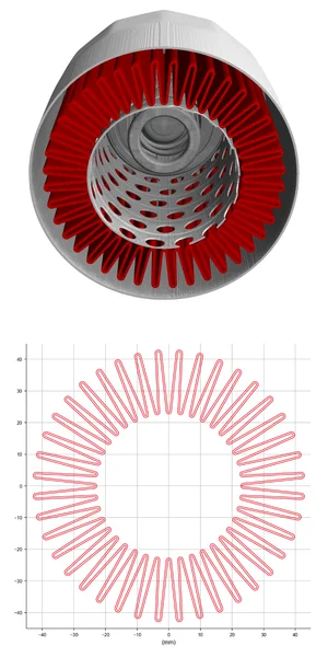
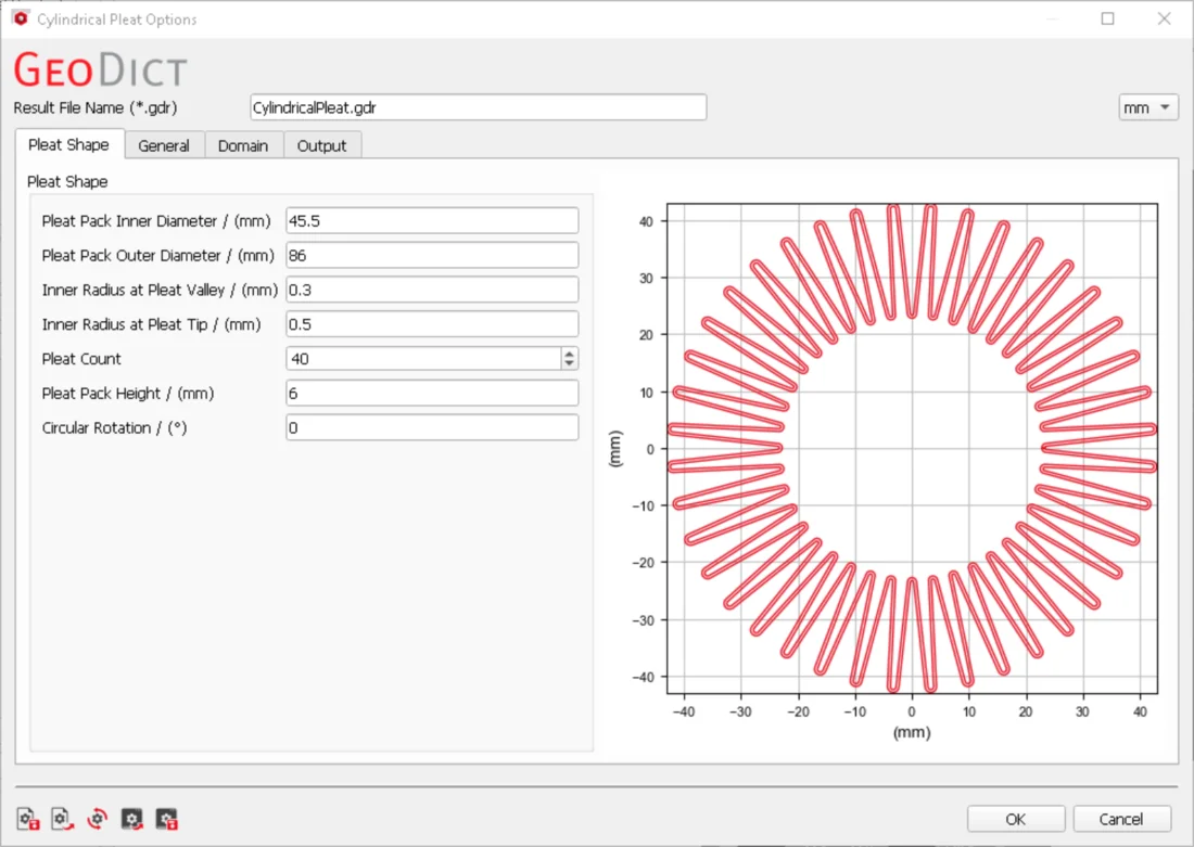
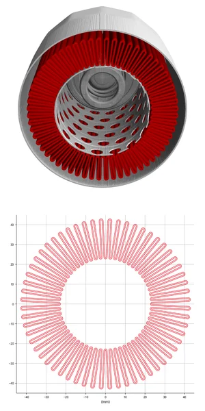
For this, several pleat counts configurations are generated using the new feature of PleatGeo to model cylindrical pleats (see Fig. 3A and Fig. 3B) [3][5]. The input parameters are the inner and outer diameter, the pleat count and the height of the pleat, as well as the inner radius at the pleat valley and tip.
After entering these values into the software, the geometry is modeled and the structure is saved as .stl. In a second step, the .stl structure is imported and voxelized to be inserted digitally at the correct location within the filter geometry. Fig. 4 shows the PleatGeo interface to enter the input parameters for the pleat generation.
After the generation of several filter geometries with changing pleat counts, computations of pressure and velocity are performed by using the FlowDict module. The (Navier-)Stokes-Brinkman equations used read as:
where, u is the velocity vector, μ is the dynamic viscosity, ρ is the density, K is the permeability and p is the pressure. These equations are solved applying the fast and memory-efficient LIR solver [1] shipped with GeoDict. The LIR solver applies adaptive meshing, which coarsens the numerical resolution in the far field and refines the resolution close to surfaces on a staggered grid scheme [2].
Furthermore, the numerical efficiency is improved by using state-of-the-art numerical methods such as multigrid and Krylov solving schemes. The Brinkman term is associated for the filter pleats, which are modelled as a porous layer with a specified material permeability, that can be obtained from measurements or simulations on the filter media scale [4]. The porous layer is necessary since, for complete filter simulations, the numerical resolution is too large to resolve individual features of the filter media.
Experimental setup:
The cylindrical filter pleats are designed in the PleatGeo module through a set of input parameters from the user. The specifications of the filter housing geometry are provided by the imported CAD files.
In the following, the original filter housing geometry and the newly designed pleat geometry are combined into a digital prototype.
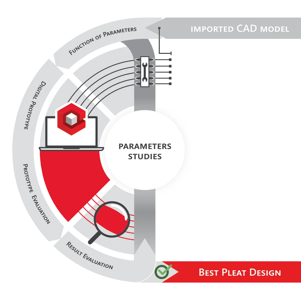
The flow properties of the prototype are evaluated digitally using FlowDict. To improve these first obtained results, the initial set of input parameters may be tuned using parametric studies.
These parameters studies to test and optimize the flow performance in a larger fashion are set up easily using Python scripts within the GeoPy environment and the cloud computation capabilities of GeoDict.
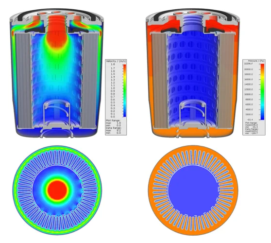
Fig. 5 shows the velocity distribution from a 2D perspective, highlighting the flow of oil through the pleats and inner netting and the cross-sectional 3D view of the entire filter. In detail, the velocity distribution shows zones of high velocity and therefore, a larger pressure loss in between the filter element and housing of the filter.
Fig. 6 presents a plot of the calculated pressure drop for several pleat count configurations. In this plot, we observe that the 56-pleats configuration shows the lowest pressure drop and therefore, a good ratio between pleat count and filter area.
Simulations performed in this study used a standard workstation featuring 16 cores. The simulations needed about 67 GB of RAM and a simulation time of around 1.4 hours each.
A set of simulations or an entire parametric study may simply be run simultaneously using the new built-in “Run-in-cloud”- button, which is shipped with the upcoming GeoDict 2023 release. This unlocks new possibilities to increase productivity and dramatically improve the time-to-market performance, especially toward deadlines and for larger systematic studies.
References:
[1] S. Linden, A. Wiegmann, H. Hagen, The LIR Space Partitioning System applied to the Stokes Equations, Graphical Models, Vol. 82 (2015) 58-66.
[2] F. H. Harlow and J. E. Welch. Numerical Calculation of Time-Dependent Viscous Incompressible Flow of Fluid with Free Surface. The Physics of Fluids, 8(12):2182|2189, 1965.
[3] A. Wiegmann, S. Rief, and D. Kehrwald. Computational Study of Pressure Drop Dependence on Pleat Shape and Filter Media. In Filtech 2007 International Conference for Filtration and Separation Technology, volume I, pages 79|86, October 2007.
[4] A. Wiegmann. Computation of the permeability of porous materials from their microstructure by FFF-Stokes. Technical Report 129, Fraunhofer ITWM Kaiserslautern, 2007.
[5] A. Wiegmann, L. Cheng, E. Glatt, O. Iliev and S. Rief. Design of pleated filters by computer simulations. In Berichte des Fraunhofer-Instituts für Techno- und Wirtschaftsmathematik (ITWM Report), Fraunhofer ITWM, Vol. 155, 2009.
